
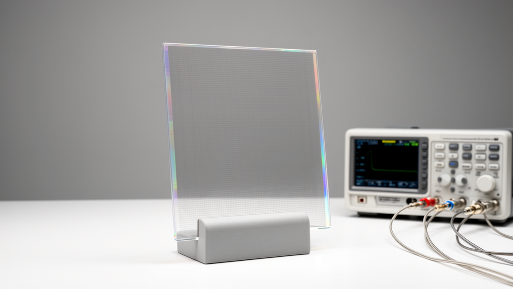
Imagine a Wi-Fi antenna hiding in plain sight—printed on a window, laminated into a smartphone display, or bonded to the smart glass of a car windshield—yet completely invisible to the human eye. A team of Greek and British researchers has now moved that vision measurably closer to reality. In a study published in Frontiers in Antennas and Propagation, engineers led by Maria Koutsoupidou of the Hellenic Army Academy, working with colleagues at the NCSR Demokritos research institute and industry partners, built and tested a fully transparent monopole antenna operating at 2.4 GHz, the frequency band used by Wi-Fi, Bluetooth, and countless Internet-of-Things devices. The antenna was made from a transparent conductive film based on a copper micromesh so fine that its metal lines are below the resolution limit of human vision, and it delivered a measured radiation efficiency of 65 percent alongside an estimated optical transmittance of 86 percent—a combination the authors describe as among the best ever reported for antennas of this type.
The central obstacle in transparent antenna research has always been a stubborn physical trade-off. Optical transparency and electrical conductivity pull in opposite directions: the more open space a film has for light to pass through, the less metal is available to carry radio-frequency current, and the more energy is lost as heat rather than radiated into space. Conductive oxides such as indium zinc tin oxide offer good transparency but suffer DC sheet resistance above 10 ohms per square in many formulations, or as low as 2 to 5 ohms per square only in multilayered films that sacrifice transmittance. Metal meshes solve the transparency problem geometrically rather than chemically, by patterning sparse metal lines that let light through the gaps, but millimeter-scale meshes are clearly visible to the naked eye, restricting them to applications like photovoltaics where aesthetics matter less.
The film used in this study, designed by Meta Materials Inc. and produced by Panasonic Industry, threads the needle with micrometer-scale geometry. It consists of copper wires 1.5 micrometers thick and 3 micrometers wide, arranged in a rectangular grid with a 45-micrometer pitch, embedded in an ultraviolet resin and supported on a flexible 58-micrometer PET substrate. Because the line width is at or below roughly 3 micrometers—close to the resolution limit of the human eye at typical viewing distances—the mesh pattern is imperceptible, making the film suitable for screens and windows without any visible structure. Optical microscope images confirmed the conductor dimensions, and spectrophotometric measurements using a JASCO V-770 UV-Vis-NIR instrument, with a halogen white light source split into reference and measurement beams, yielded a total optical transmittance of 86 percent. That figure includes an 8 percent reflection loss from the two film-air interfaces, meaning the antenna achieved this transparency without antireflection coatings.
Characterizing the film’s electrical behavior at microwave frequencies proved to be a crucial step, and one where the researchers departed from common practice. At radio and microwave frequencies, current flows only within a thin surface layer of a conductor due to the skin effect. For copper at 2.4 GHz, the skin depth is approximately 1.35 micrometers—comparable to the thickness of the micromesh lines themselves. This confinement, combined with the narrow and sparse geometry of the mesh, dramatically increases the effective surface resistance compared with what a DC measurement would suggest. The team therefore measured the film’s complex surface impedance across the 2.0 to 3.3 GHz range using a waveguide transmission method: two WR 340 rectangular waveguides, with 110 by 68 millimeter samples covering the waveguide gap, measured transmission and reflection coefficients from which the impedance was extracted. Two independent extraction approaches, using a substrate permittivity of 3.2 and a reference measurement of bare PET, agreed to within 1 percent.
The result at 2.4 GHz was a complex surface impedance of 1.25 plus j0.33 ohms per square. A four-point probe measurement of the DC sheet resistance gave a lower value of 0.85 ohms per square, and the difference is physically meaningful rather than experimental noise. DC measurements cannot account for current confinement by the skin effect or for the distributed inductive reactance introduced by the mesh geometry, where increased magnetic flux linkage between sparsely spaced conductors contributes to the imaginary part of the impedance. To first order, the surface resistance of a mesh scales inversely with the metal fill factor, so widening the pitch raises both resistive and inductive components, degrading microwave performance even as it improves optical transparency. By feeding the measured high-frequency impedance into their simulations instead of the DC value, the researchers enabled far more accurate modeling of the antenna at its operating frequency.
With the material characterized, the design challenge was to choose an antenna topology that compensates for the film’s limited conductivity. The team selected a planar monopole with a short ground plane—a deliberately simple geometry with no narrow high-current-density features and no lossy transmission lines. The substrate was a 40 by 55 by 1.2 millimeter PET slab with permittivity 3.0 and loss tangent 0.008; the ground plane measured 40 by 11.5 millimeters, and the monopole length was 38.4 millimeters. In simulations performed with CST Studio Suite, the micromesh was represented as a homogenized conductive layer using the measured impedance rather than its explicit wire topology. A parametric analysis revealed that the monopole width W is the key efficiency lever: widening the strip reduces the effective current density on the conductor surface and therefore the ohmic losses. When W was systematically varied—with substrate thickness adjusted to maintain resonance at 2.4 GHz and a 50-ohm match—radiation efficiency improved consistently with increasing width, confirming the effect came from the wider current path rather than from substrate changes, which are known to reduce efficiency on their own.
Fabrication was a study in practical ingenuity. The conductive film parts were cut with a CNC laser cutter and adhered, conductive face up, to the PET slab using optically clear adhesive. Because soldering would burn the PET components, the team designed and 3D printed a clothing-pin-like fixture from Z-HIPS material, with permittivity 2.2 and loss tangent 0.002 at 2.5 GHz, to attach the SMA connector and encircle it, ensuring galvanic connection between the transparent radiating element, the transparent ground plane, and the connector’s metal parts. The available PET substrate thickness of 1.2 millimeters set the final monopole width at 3.1 millimeters. Measurements were then carried out in the anechoic chamber at NCSR Demokritos using an Anritsu MS46122A vector network analyzer and a bazooka balun to feed the antenna cleanly.
The experimental results validated the design strategy. The measured reflection coefficient agreed well with simulations, and the measured gain was 0.6 dBi against a simulated 1.4 dBi, with the radiation pattern measured at 2.4 GHz using a time-gating technique to suppress unwanted scattering from the antenna’s omnidirectional pattern. The measured radiation efficiency at 2.4 GHz was 65 percent for the antenna built from the film with 1.25 ohms per square surface impedance. Simulation of the surface current distribution confirmed that the highest current densities concentrate along the monopole strip and near the feed region, exactly where ohmic losses are most significant. The authors attribute the modest discrepancy between measured and simulated efficiency to a likely underestimation of the film’s reactance during the waveguide measurement, arising from the micro-structured wire network.
Placed in context, these numbers represent a genuine advance. Among transparent antennas operating in comparable frequency ranges, materials with optical transmittance of 70 to 75 percent typically correspond to radiation efficiencies of roughly 40 to 53 percent: a rectangular patch on acrylic reached 43 percent efficiency at 62 percent transmittance, a dual-band patch on PDMS achieved 37 percent at 70 percent, meandered monopoles on glass delivered 46 percent at 75 percent, and a slot antenna integrated into a smart-glasses frame measured about 40 percent at 2.4 GHz. The highest previously documented transmittance for a metal micromesh film used in a transparent microwave antenna was 75 percent. An 85-percent-efficient stacked circular patch does exist, but it relies on vias and central full-metal patches that partially obstruct visibility. The new antenna, by contrast, is entirely transparent—both radiating element and ground plane—making its 65 percent efficiency the highest reported for antennas fully constructed from transparent metal-mesh films with transmittance exceeding 70 percent.
The implications reach well beyond the laboratory. Antennas with this performance level are sufficient for short-range and near-field wireless applications where unobstructed visibility is critical: window-mounted IoT gateways, transparent access points integrated into displays or smart glass, vehicular and architectural interfaces, and wearable devices. The researchers note that replacing the PET substrate with PMMA or glass could push overall transmittance higher still without altering electromagnetic behavior, and that selectively reinforcing high-current-density regions with conventional metal offers a complementary path to further efficiency gains while preserving visual transparency. More broadly, the work demonstrates that the transparency-efficiency trade-off is not dictated by materials alone: by deliberately choosing a geometry that distributes RF current over a larger conductor cross-section, engineers can shift transparent antennas toward a more favorable region of the performance space. As demand grows for wireless infrastructure woven invisibly into windows, vehicles, and screens, antennas that work as well as they hide may soon be everywhere—and nowhere to be seen.
,
Subject of Research: Transparent conductive film antenna
Article Title: Development and testing of an antenna made of an optically transparent conductive film
Article References: Koutsoupidou, M., Paraskevopoulos, A., Rompolas, D., Dovelos, K., Sotiriou, I., Zervos, T., Tzarouchis, D. C., Alexandridis, A., Kallos, E., & Kosmas, P. (2026). Development and testing of an antenna made of an optically transparent conductive film. Frontiers in Antennas and Propagation, 4, Article 1719187. https://doi.org/10.3389/fanpr.2026.1719187
Image Credits: AI Generated
DOI: 10.3389/fanpr.2026.1719187
Keywords: transparent antenna, transparent conductive film, micromesh, 2.4 GHz, radiation efficiency, antenna design, IoT, Development, testing, antenna, made, optically
Cite Scienmag News
Scienmag. (October 16, 2026). Invisible antenna made of transparent conductive film hits 65% efficiency. https://scienmag.com/invisible-antenna-made-of-transparent-conductive-film-hits-65-efficiency/
Scienmag. "Invisible antenna made of transparent conductive film hits 65% efficiency." Scienmag, 16 October 2026, https://scienmag.com/invisible-antenna-made-of-transparent-conductive-film-hits-65-efficiency/. Accessed 16 October 2026.
Scienmag. "Invisible antenna made of transparent conductive film hits 65% efficiency." Scienmag. October 16, 2026. https://scienmag.com/invisible-antenna-made-of-transparent-conductive-film-hits-65-efficiency/