

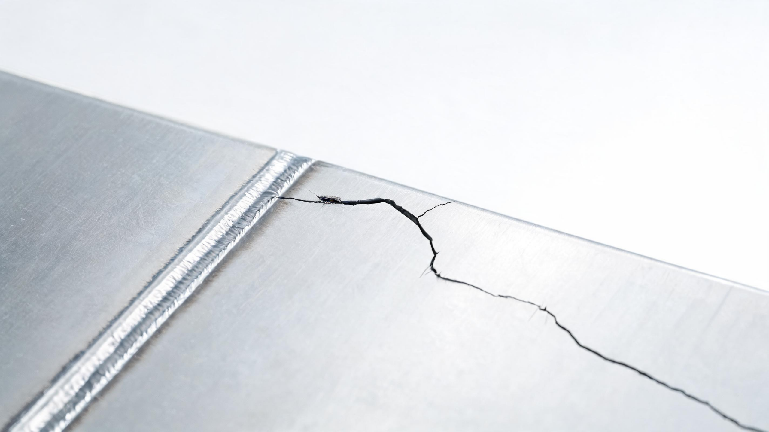
A hidden defect only a fraction of a millimeter long can determine where a friction stir weld ultimately breaks, according to a finite element study of 6082-T6 aluminum alloy. The analysis shows that failure is controlled by a competition between two features created during welding: a root defect, which acts like a small crack near the underside of the joint, and the continuously varying material properties produced by the welding heat. When the defect is short or favorably oriented, the weld behaves much like a defect-free joint and concentrates deformation in the heat-affected zone. When the defect becomes sufficiently long or points through the plate at a critical angle, strain shifts into the weld nugget zone and the defect itself becomes the dominant driver of fracture. The results provide a quantitative way to connect an internal flaw with the visible deformation that develops on a weld’s top surface.
Friction stir welding is widely used to join aluminum components because it produces a bond without melting the workpieces. A rotating tool travels along the interface, generating frictional heat and mechanically stirring softened metal. The process is used in applications including aviation, aerospace, railways and shipbuilding, where joints may form part of a structure that must carry substantial loads. Yet the solid-state process is not immune to defects. Insufficient material flow can leave a root defect, often appearing as a micro-crack or incomplete-penetration feature within the weld nugget zone. At the same time, the thermal cycle changes the microstructure and strength from one region of the joint to another. The center of the weld, the surrounding heat-affected zone and the unaffected base metal therefore do not respond identically when the joint is pulled.
That combination creates a difficult engineering problem. A defect weakens the material locally, but the weakest region created by the thermal cycle may lie somewhere else. Under tension, the joint does not simply fail at the largest visible or nominally weakest feature; instead, strain accumulates according to the interaction between geometry and local mechanical properties. Previous experiments had shown that root-defect orientation and length can change the fracture location, but the underlying competition was not fully quantified. The new model was developed by Jiebin Zhan, Qingyu Shi, Qilei Dai, Kun Xu, Mengran Zhou and Gaoqiang Chen to examine both influences in the same simulation. Their focus was 5-millimeter-thick 6082-T6 aluminum welded at a tool rotation speed of 1,800 revolutions per minute and a travel speed of 600 millimeters per minute.
The researchers first modeled the heat generated by the rotating tool and used the resulting temperature history to assign spatially varying material properties throughout the weld. The simulated thermal field formed a bowl-shaped region on the transverse section, with a calculated maximum temperature of 492.8 degrees Celsius. The yield limit, the stress at which permanent deformation begins, was lower in the weld than in the base metal, whose modeled value was 275 megapascals. Moving outward from the weld center, the yield limit first decreased and then increased, reflecting the combined effects of the thermal cycle and age hardening in the precipitation-strengthened alloy. Rather than treating the weld as a uniform block, the model mapped this continuous property variation into the tensile calculation. This step allowed the simulation to represent how neighboring regions with different strengths share and redistribute load.
Root defects were introduced as initial cracks at the weld center, and the extended finite element method was used to follow their behavior without repeatedly rebuilding the computational mesh. The simulations included a defect-free model and models with defects measuring 100, 200, 300, 400 and 500 micrometers, as well as models with a 500-micrometer defect placed at orientations of 30, 45, 60, 90, 120, 135 and 150 degrees. In the study, the orientation angle was measured between the tensile loading direction and the defect. The model allowed a crack to propagate in the direction of maximum principal stress when the maximum principal strain exceeded 0.1, with damage evolution represented through energy-based linear stiffness softening. This framework linked the local stress and strain fields to the point at which a defect opened, propagated or remained relatively inactive.
The numerical predictions agreed closely with measurements from tensile tests. In the experiment, a root defect longer than 500 micrometers was found near the weld center and was nearly perpendicular to the bottom surface. That specimen failed in the weld nugget zone, while a comparative defect-free weld failed in the heat-affected zone. Digital Image Correlation, an optical method that tracks surface movement during loading, showed the same shift in strain concentration. The model predicted a weld yield limit of 148.91 megapascals, compared with a measured value of 148.27 megapascals, an error of 0.43 percent. Its predicted ultimate tensile strength was 212.99 megapascals, compared with 221.47 megapascals measured experimentally, an error of 3.83 percent. The close agreement supported using the model to investigate defect sizes and orientations that were not all directly tested.
The simulations revealed two distinct failure patterns. In the first, called Mode I in the study, strain concentrated in the heat-affected zone, as it does in a defect-free joint. A short root defect could open at the weld center without continuing to propagate, while the heat-affected zone accumulated more tensile strain and remained the likely fracture location. In the second pattern, Mode II, the defect tip in the weld nugget zone became the dominant concentration point. For defects 400 and 500 micrometers long, the simulated crack initiated and propagated along the root defect. At 200 and 300 micrometers, the defect opened but did not continue propagating, while a 100-micrometer defect produced no modeled damage in the weld nugget zone and left the heat-affected zone as the critical region. The transition was not a simple on-off response: it emerged as the competing strain concentrations gradually exchanged dominance.
For defects oriented perpendicular or nearly perpendicular to the workpiece bottom surface, the shift toward weld-nugget failure was also strongest. In the 500-micrometer cases, the maximum tensile-direction strain in the weld nugget zone rose from 0.0925 at 30 degrees to 0.1237 at 90 degrees, an increase of 33.73 percent. From 150 degrees toward 90 degrees, it increased from 0.0878 to 0.1237, a rise of 40.89 percent. The researchers inferred a critical defect length of 340.1 micrometers under the selected welding conditions. They also identified a critical orientation range from 37.9 to 140.9 degrees. Above the length threshold, or within that orientation range, the weld-nugget strain exceeded the heat-affected-zone strain and the defect had a significant effect on load-bearing behavior. These values are specific to the alloy, plate thickness, welding parameters and modeling assumptions, rather than universal acceptance limits for every friction stir weld.
The study also identified why the transition occurs and suggested a practical way to detect its consequences. The heat-affected zone showed relatively consistent strain-growth behavior as defect length changed, while the defect tip in the weld nugget zone became more rapidly strained and retained a higher strain-increase rate as the defect grew. The relative strain at the two locations reversed between 300 and 400 micrometers, consistent with the calculated 340.1-micrometer threshold. Because internal strain and stress are difficult to measure during service, the researchers examined the weld’s top surface as a proxy. Changes in surface tensile strain were concentrated within about 10 millimeters of the weld center, and defects 400 or 500 micrometers long produced a notable increase at a position 3.8 millimeters from that centerline. Surface stress showed a similar pattern. The proposed approach could therefore support model-based assessment of hidden defects, although the authors note that additional calibration would be needed for other materials, welding conditions, loads and defect types.
The central contribution of the analysis is not simply the identification of a dangerous defect size, but the treatment of fracture location as a field interaction problem. In a welded joint, strength varies continuously across the transverse section rather than changing abruptly at the boundaries between base metal, heat-affected material and weld nugget. A root crack therefore modifies an already non-uniform stress field. The same geometric flaw can remain secondary when the surrounding material distribution directs deformation toward the heat-affected zone, yet become decisive when its tip produces a sharper concentration than the thermally weakened region.
This interpretation helps explain why defect inspection based only on length may be incomplete. Orientation determines how effectively the applied tensile load opens the defect and how its tip interacts with the local material response. A crack with a similar measured length can consequently have different structural significance depending on its inclination and position. The inferred transition values—340.1 micrometers for length and 37.9° to 140.9° for orientation—should therefore be understood as outcomes of the specified alloy, thickness, welding parameters, loading configuration and constitutive assumptions. They are mechanistic indicators for this modeled system, not universal defect-acceptance thresholds.
The framework also illustrates the value of combining experiments with simulation in weld assessment. Digital Image Correlation supplies an observable surface response, while the finite element model connects that response to hidden conditions at the weld root and to the evolving fields inside the joint. Such a connection could help distinguish a defect that is present but mechanically inactive from one that is likely to control failure under tension. Before being used for service decisions, however, the approach would need validation across additional weld geometries, process conditions, loading modes and defect morphologies. The study consequently offers both a predictive tool and a basis for prioritizing inspection: internal flaws should be evaluated together with the surrounding spatial distribution of properties, rather than treated as isolated geometric discontinuities.
Subject of Research: Tensile failure mechanisms in defective friction stir welded aluminum joints
Article Title: Competition between root defects and non-uniform properties in governing the tensile deformation behavior of friction stir welds: a finite element analysis
Article References: Zhan, J., Shi, Q., Dai, Q., Xu, K., Zhou, M., & Chen, G. (2026). Competition between root defects and non-uniform properties in governing the tensile deformation behavior of friction stir welds: a finite element analysis. Advanced Materials Joining, 1(1), Article 13. https://doi.org/10.1007/s44500-026-00015-y
Image Credits: AI Generated
DOI: 10.1007/s44500-026-00015-y
Keywords: friction stir welding, root defects, aluminum alloys, finite element analysis, tensile deformation, weld failure, heat-affected zone, weld nugget zone, Competition, between, root, defects
Cite Scienmag News
Denise Maddox. (August 28, 2026). Tiny Weld Defects Can Redirect How Aluminum Joints Break. Scienmag. https://scienmag.com/tiny-weld-defects-can-redirect-how-aluminum-joints-break/
Denise Maddox. "Tiny Weld Defects Can Redirect How Aluminum Joints Break." Scienmag, 28 August 2026, https://scienmag.com/tiny-weld-defects-can-redirect-how-aluminum-joints-break/. Accessed 5 October 2026.
Denise Maddox. "Tiny Weld Defects Can Redirect How Aluminum Joints Break." Scienmag. August 28, 2026. https://scienmag.com/tiny-weld-defects-can-redirect-how-aluminum-joints-break/