

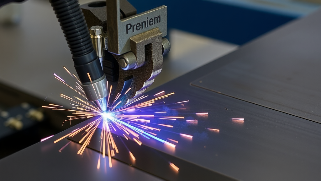
Welding thick steel plates is one of those deceptively simple industrial operations that hides a ferocious physics problem. When an arc melts metal at thousands of degrees and the joint cools, the material shrinks unevenly, locking in stresses that can warp entire structures and quietly shorten their fatigue life. In ship hulls, offshore platforms, power plants and steel skyscrapers, controlling that hidden stress landscape is the difference between a joint that lasts decades and one that cracks under cyclic loading. A team of researchers from Osaka University’s Joining and Welding Research Institute, Tanta University and Japan Fabtech has now put a new groove design for horizontal welding of thick plates through one of the most thorough stress-and-distortion audits published to date, combining precision measurement with high-fidelity simulation.
The design at the center of the study is a narrow slanted groove, a hybrid between the two conventional options that dominate thick-plate work. Traditional V-shaped or bevel grooves are forgiving but voracious: their wide openings demand large volumes of filler wire and heavy heat input, which drives up cost and accumulates thermal energy in the joint. Narrow-gap I-grooves sit at the opposite extreme, consuming minimal filler metal, but in horizontal welding they are notoriously prone to defects such as lack of penetration and solidification cracking. The slanted groove threads the needle. Its cross-sectional area falls between the two conventional geometries, cutting filler consumption well below bevel levels, while its inclined walls reshape the weld bead to suppress the cracking mechanism that plagues I-grooves.
The cracking problem is rooted in bead geometry. When the height-to-width ratio of a weld bead exceeds roughly one, the last-to-solidify liquid at the weld centerline becomes starved, unable to feed the shrinkage strains concentrating there. Columnar grains grow along the centerline, shrinkage stresses build, and hot cracks can tear through the semi-solid metal. Lowering that ratio below one improves liquid feeding and suppresses cracking. The slanted groove achieves exactly this by tilting the groove walls at 35 and 37 degrees, so the wire sits nearly parallel to the groove surface rather than the horizontal plane. That orientation places the welding position between conventional horizontal and flat welding, boosting penetration on the upper sidewall, which gravity and arc forces normally shortchange in horizontal work.
To test the concept, the researchers welded two 36-millimeter-thick plates of SN490B structural steel, each measuring 133.26 by 250 millimeters, using CO2-shielded arc welding with YGW18 wire in thirteen passes, with no preheating or post-weld treatment. Two transverse webs and a backing strip, all of the same steel, mimicked the restraint of a real structure. A thermocouple recorded the temperature history near the weld line throughout the process, and after welding the team measured angular distortion across four transverse sections using a flat reference plate and magnetic blocks. The average total transverse bending angle came out at 0.68 degrees, comfortably inside the one-degree acceptance limit for angular distortion in welded construction.
Mapping the residual stresses demanded heavier instrumentation. The team used the contour method, in which the specimen is sliced down the middle with wire electro-discharge machining, releasing the stress perpendicular to the cut and causing the surface to deform. A Keyence VR-5200 structured-light system scanned that deformed surface with ten-micrometer precision, and the measured displacements were fed into a finite element model to reconstruct the internal stress field. Because the contour method alone captures only one stress component, the researchers combined it with X-ray diffraction on electropolished measurement lines, an approach known as the extended contour method, to recover the full three-dimensional residual stress state on the cut surface.
The measurements told a consistent story. Longitudinal residual stress, running along the weld line, was high and tensile throughout the weld layers and the adjacent heat-affected zone, peaking at roughly 650 megapascals in the molten zone on the surface path, a consequence of constrained longitudinal shrinkage and heat accumulation inside the narrow groove. Moving away from the weld, the stress fell and turned compressive, and through the thickness it was highest near the top surface, where the final passes were deposited, declining toward the bottom. Transverse stresses were lower overall but still showed pronounced tensile peaks in the weld zone, with oscillations along the thickness path that trace the sequential thermal cycles of the thirteen individual passes.
On the computational side, the team built a three-dimensional thermo-elastic-plastic finite element model in JWRIAN, an in-house welding simulation code developed at Osaka University. The model contained about 61,000 nodes and 56,000 hexagonal solid elements, finely meshed in the weld zone and coarsening outward. An uncoupled thermal-mechanical scheme first computed the temperature history using a prolate-spheroid heat source with temperature-dependent material properties, then applied that history as a thermal load in an elastic-plastic large-deflection analysis. The simulated weld pool geometry matched the macro-etched cross-sections, and the calculated temperature at the monitored point tracked the measured curve closely across all thirteen passes.
One refinement proved decisive for stress prediction. Vickers hardness testing showed the molten zone to be harder than the base metal, while the heat-affected zone differed only slightly. The team translated those hardness ratios directly into yield-strength variations, raising the molten zone’s yield stress by roughly twenty percent across the temperature range while leaving the heat-affected zone essentially unchanged. Incorporating this hardness-based yield strength significantly improved the agreement between predicted and measured residual stresses in both the longitudinal and transverse directions, a practical demonstration that microstructural data can sharpen welding simulations without exotic material testing.
The simulated distortion also matched experiment, with a predicted average angular distortion of 0.53 degrees against the measured 0.68 degrees. Intriguingly, both revealed that the distortion is not symmetric about the weld line: the acute-angle side of the slanted joint rotated more than the obtuse side, because the inclined geometry converts symmetric shrinkage into asymmetric angular rotation, unlike conventional grooves. The finite element results further showed peak tensile longitudinal stress near the final passes of about 700 megapascals, compressive stresses of roughly minus 70 to minus 90 megapascals at mid-thickness to satisfy equilibrium, and Von Mises equivalent stress approaching the material’s yield strength of 458 megapascals near the last few passes.
Taken together, the results argue that the narrow slanted groove delivers a rare combination in thick-plate welding: sound welds free of the defects that plague I-grooves, filler consumption far below bevel-groove levels, distortion within standard acceptance limits, and residual stresses that are now quantitatively predictable. For industries joining thick steel in the horizontal position, from shipyards to offshore construction, the study offers both a practical groove design and a validated simulation workflow, complete with a hardness-informed material model, that could move straight from the laboratory into fabrication planning.
Subject of Research: Residual stress and deformation in horizontal multi-pass welding of thick steel plates with a narrow slanted groove
Article Title: Horizontal welding deformation and residual stress of narrow slanted groove for thick plates
Article References: Nour, M., Rashed, S., Ma, N., Agano, Y., Okumura, T., & Shibahara, M. (2026). Horizontal welding deformation and residual stress of narrow slanted groove for thick plates. Advanced Materials Joining, 1(1), Article 16. https://doi.org/10.1007/s44500-026-00020-1
Image Credits: AI Generated
DOI: 10.1007/s44500-026-00020-1
Keywords: welding, thick steel plates, narrow slanted groove, residual stress, angular distortion, contour method, X-ray diffraction, finite element analysis, multi-pass welding, solidification cracking, SN490B steel, hardness
Cite Scienmag News
Denise Maddox. (September 24, 2026). Slanted Groove Welding Tames Distortion in Thick Steel Plates. Scienmag. https://scienmag.com/slanted-groove-welding-tames-distortion-in-thick-steel-plates/
Denise Maddox. "Slanted Groove Welding Tames Distortion in Thick Steel Plates." Scienmag, 24 September 2026, https://scienmag.com/slanted-groove-welding-tames-distortion-in-thick-steel-plates/. Accessed 4 October 2026.
Denise Maddox. "Slanted Groove Welding Tames Distortion in Thick Steel Plates." Scienmag. September 24, 2026. https://scienmag.com/slanted-groove-welding-tames-distortion-in-thick-steel-plates/