

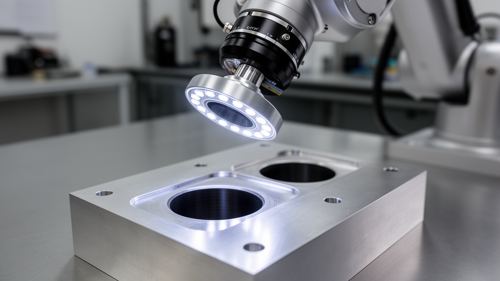
Blind holes are everywhere in modern engineering, from cooling channels in turbine blades to fastener sockets in aircraft fuselages and drilled passages in engine castings, yet they remain one of the most stubborn measurement problems in manufacturing. Unlike through holes, their inner walls and bases are hidden from direct view, so coordinate measuring machines struggle with long setup times, tactile probes risk bending or scratching delicate surfaces, and conventional cameras simply cannot see far enough into the cavity. A new study published in Frontiers in Artificial Intelligence now reports a robotic system that combines artificial intelligence, adaptive lighting and error-compensated robot calibration to locate and size blind holes without ever touching them, achieving an average three-dimensional position error of just 0.0322 millimeters across thirty physical trials.
The research, carried out by Giriraj Mannayee of the School of Mechanical Engineering at Vellore Institute of Technology in India, addresses a gap that has long separated two mature but disconnected fields. Optical vision metrology is remarkably accurate when the boundary of a circular hole is fully visible; recent robot-vision studies have reported mean diameter errors as low as 0.016 millimeters on optically accessible holes, and binocular systems for satellite assembly have reached positioning accuracies of 0.06 millimeters. Blind holes, however, are a fundamentally different problem. Their interiors are poorly illuminated, machined metal surfaces throw specular reflections that masquerade as false edges, oblique viewing angles distort the apparent geometry through perspective, and optical signal quality degrades rapidly as depth grows relative to diameter.
The proposed architecture stacks six functional layers into a single closed measurement loop. A six-axis industrial robot positions a compact optical head carrying an industrial camera, a low-distortion telecentric lens, an LED or laser source, an optical diffuser and an optional depth sensor. An adaptive illumination layer then treats light not as a passive imaging tool but as an actively controlled measurement parameter: a closed-loop controller adjusts emission intensity to maximize a quantitative image-quality index built from contrast, edge sharpness and saturation, tuned to the depth and reflectance of each specific hole. The physics behind this is straightforward. Reflected intensity depends on emitted intensity, surface reflectance, incidence angle and optical depth, so a fixed illumination setting will overexpose polished surfaces and underexpose dark, conventionally machined ones.
At the heart of the vision pipeline sits a lightweight convolutional neural network encoder-decoder with roughly 1.2 million trainable parameters. Operating on 256 by 256 pixel RGB images, it produces a pixel-wise probability map of the valid optical region inside the hole, deliberately trained to separate genuine optical data from reflection artifacts on the inner walls rather than merely finding the visible outer boundary. Crucially, the network is optimized with a hybrid loss function that combines segmentation loss, edge or contour loss and a geometric residual loss, the last of which penalizes masks that look visually plausible but would bias the fitted dimensions. The training images were captured under varied lighting, orientation and background conditions, and the thirty experimental measurement images were kept entirely disjoint from the training and validation sets to prevent information leakage.
Once the segmentation mask is thresholded at a fixed confidence value of 0.50, boundary points are refined to sub-pixel accuracy by interpolating along the intensity gradient of the smooth probability map, locating edges more precisely than the camera’s native pixel resolution. Near-normal views are fitted with a robust circle model, while oblique views are fitted with a general conic and then iteratively corrected through the camera model to recover the true circular geometry across approach angles from 0 to 20 degrees. Finally, the measured hole center is transformed from the camera frame into the robot base frame through hand-eye calibration, and a data-driven error-compensation model, trained on ground-truth coordinates from a coordinate measuring machine conforming to the ISO 10360 standard, removes residual systematic errors arising from robot kinematics, calibration and illumination.
The experimental validation involved thirty CNC-machined blind holes in an acrylic block approximately 100 by 80 by 50 millimeters, spanning diameters of 5 to 15 millimeters, depths of 10 to 45 millimeters, realized depth-to-diameter ratios of 2.0 to 3.1, and three surface finishes representing roughly 20, 50 and 80 percent reflectance. Every hole was first measured by the robotic system and then by a CMM as the reference. All thirty trials succeeded, yielding a mean three-dimensional position error of 0.0322 millimeters with a 95 percent bootstrap confidence interval of 0.028 to 0.037 millimeters, a root-mean-square error of 0.0344 millimeters, and a worst-case error of 0.0645 millimeters, more than an order of magnitude inside the study’s 1-millimeter sub-millimeter target and well within its stricter 0.5-millimeter goal.
Diameter measurement proved nearly as strong. The mean absolute diameter error was 0.0544 millimeters, with an RMSE of 0.0647 millimeters and a maximum of 0.1607 millimeters, while the average repeatability standard deviation across repeated measurements was 0.0217 millimeters. Mean AI segmentation confidence reached 0.935. Perhaps the most striking result concerns the adaptive lighting: the controller automatically reduced emitted intensity from about 149 percent for low-reflectivity surfaces to about 110 percent for medium and 77 percent for high-reflectivity ones, and mean position errors stayed within a narrow band of 0.026 to 0.037 millimeters across all three reflectivity classes, exactly the behavior the diffuse-reflection model predicts a fixed-illumination system could not deliver. The differences among reflectivity classes did not reach statistical significance at this sample size, and reflectivity was partially confounded with approach angle in the design, so the class averages should not be read as pure reflectivity effects.
Correlation analysis revealed that hole depth, not reflectivity, is the dominant driver of declining AI confidence, with a Pearson coefficient of −0.959 between depth and confidence. Detection nonetheless remained at 100 percent across the full 10-to-45-millimeter depth range. Approach angle emerged as the main accuracy risk: at angles of 15 degrees or more, mean position error rose roughly 50 percent, from 0.028 to 0.041 millimeters, a statistically significant increase even after Bonferroni correction, though still far below the 0.5-millimeter threshold. Position error and diameter error showed almost no intercorrelation, suggesting they stem from distinct error sources and should be compensated separately in the systematic error model.
The author is careful to frame these results as proof of concept rather than industrial certification. Thirty single-replicate trials cannot support extrapolation beyond the tested envelope, depth and diameter were partially confounded in the design, reflectivity and approach angle overlapped across classes, and no hardware ablation was performed, so the individual contributions of adaptive illumination, AI segmentation, sub-pixel fitting and robot compensation cannot yet be quantified. The workpieces were acrylic rather than metal, no fixed-illumination baseline was measured, and depth-to-diameter ratios above 3.1, where optical occlusion becomes severe, remain untested. Future work will include controlled ablation studies, larger and better-balanced datasets, metallic industrial parts, and validation at the deep-hole ratios of 5 to 10 that matter most for turbine and hydraulic applications.
Even with those caveats, the implications are considerable. A robot that can inspect blind holes in place, without removing parts to a CMM, could bring metrology directly onto machining lines, additive manufacturing cells and assembly stations in aerospace, automotive and medical device production, using the same machine that manufactures the part to verify it. The finding that AI segmentation confidence behaves as a near-linear proxy for optical attenuation also opens the door to online decision-making, where the system itself decides when a hole is too deep for a reliable pass and schedules re-illumination or a second approach. Further validation on real metallic components and deeper hole geometries will determine whether this combination of adaptive illumination, AI segmentation and CMM-anchored robot compensation can mature into a routine tool for measuring geometry that traditional probes have never been able to reach.
Subject of Research: AI-assisted adaptive-optical robotic metrology for non-contact localization and dimensional measurement of blind holes
Article Title: AI-assisted adaptive-optical robotic metrology for sub-millimeter localization and dimensional measurement of blind holes
Article References: Mannayee, G. (2026). AI-assisted adaptive-optical robotic metrology for sub-millimeter localization and dimensional measurement of blind holes. Frontiers in Artificial Intelligence, 9, Article 1983856. https://doi.org/10.3389/frai.2026.1983856
Image Credits: AI Generated
DOI: 10.3389/frai.2026.1983856
Keywords: robotic metrology, blind hole measurement, adaptive illumination, AI segmentation, machine vision, robot-camera calibration, sub-pixel localization, precision manufacturing, coordinate measuring machine, optical sensing, dimensional inspection, AI-assisted
Cite Scienmag News
Denise Maddox. (October 26, 2026). AI-guided robot with adaptive lighting measures blind holes to 0.03 mm accuracy. Scienmag. https://scienmag.com/ai-guided-robot-with-adaptive-lighting-measures-blind-holes-to-0-03-mm-accuracy/
Denise Maddox. "AI-guided robot with adaptive lighting measures blind holes to 0.03 mm accuracy." Scienmag, 26 October 2026, https://scienmag.com/ai-guided-robot-with-adaptive-lighting-measures-blind-holes-to-0-03-mm-accuracy/. Accessed 26 October 2026.
Denise Maddox. "AI-guided robot with adaptive lighting measures blind holes to 0.03 mm accuracy." Scienmag. October 26, 2026. https://scienmag.com/ai-guided-robot-with-adaptive-lighting-measures-blind-holes-to-0-03-mm-accuracy/