

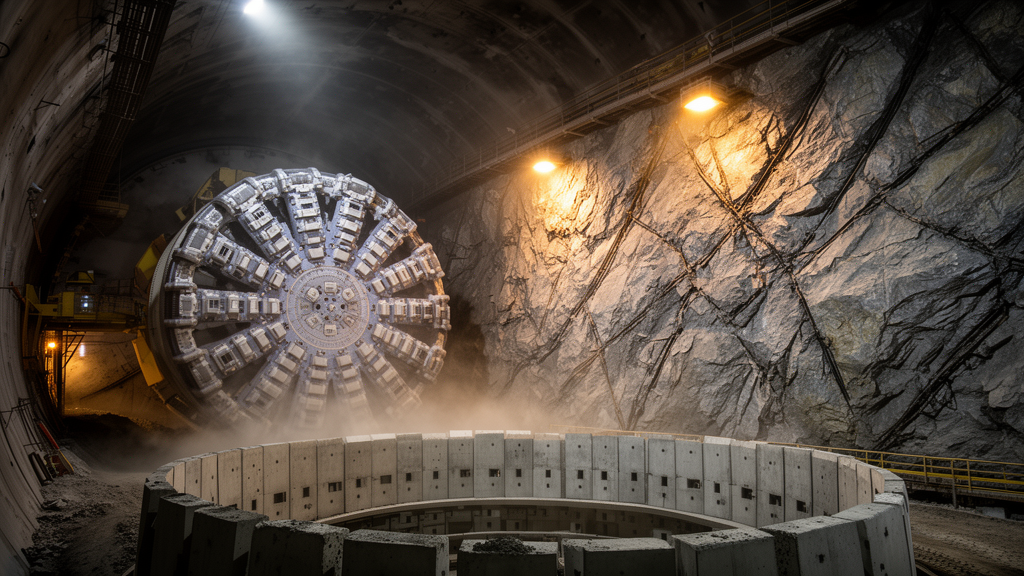
An open-type tunnel boring machine can chew through hard rock far faster than conventional drilling and blasting, but in China’s coal mines that speed comes with a hidden vulnerability. Because the cutterhead and front structure of the machine occupy the space immediately behind the excavation face, crews cannot install complete support for roughly the first three meters of newly cut roadway. In rock masses laced with persistent geological joints, that short delay can be enough to trigger block detachment and local collapse. A new numerical and field study at the Yuandian No. 2 Coal Mine in northern Bozhou, Anhui Province, now quantifies exactly how the geometry and strength of those joints govern where and how badly the surrounding rock fails.
The research, published in Frontiers in Physics, was carried out by Xinran Xue of Jiangsu College of Engineering and Technology and Kai Zhang, Bosong Yu, and Lianjie Fu of China University of Mining and Technology. The team applied a three-dimensional Ubiquitous-Multiple-Joint model, a continuum formulation that embeds multiple virtual joint planes within every zone of the rock matrix and assigns separate failure criteria to the matrix and to each joint set. This allowed them to run comparative sensitivity analyses of progressive TBM excavation and delayed support, isolating the effects of joint orientation, the number of joint sets, and joint bonding strength under otherwise identical conditions.
The modeled roadway was 4.88 meters in diameter, matching the two haulage roadways the mine’s open-type TBM is driving through the seventh mining area. The numerical block measured 60 by 50 by 50 meters and contained 187,000 elements, with the mesh refined around the tunnel. In situ stresses taken from mine records were applied as boundary loads: 27.9 MPa parallel to the roadway axis, 16.8 MPa perpendicular, and 19.5 MPa in the intermediate direction. Excavation was simulated with a material-softening procedure in which the stiffness of excavated elements was reduced linearly to zero over 1,000 calculation steps, reproducing the gradual unloading a real TBM imposes as its cutters advance.
The first sensitivity sweep varied joint orientation across seven cases, combining dip angles from horizontal to vertical with strike angles from parallel to perpendicular to the drive direction. The results were striking. For vertically dipping joints, rotating the strike angle from 0 degrees to 90 degrees relative to the roadway axis increased the plastic-zone volume from 14.0 to 41.0 cubic meters and the maximum displacement from 12.5 to 58.9 millimeters, nearly a fivefold jump in deformation. When joints dipped vertically and struck parallel to the tunnel, the plastic zone formed a uniform annulus of pure rock-matrix shear failure, meaning the joints were never activated. When the strike was perpendicular, joint shear and mixed failure concentrated on both sidewalls, producing severe bilateral convergence.
That pattern carried a practical message: the strike angle determines the preferred direction of joint-controlled failure, particularly for steeply dipping joints. In the worst case, joint-related failure accounted for roughly three-quarters of the total plastic-zone volume, including about 13.4 cubic meters of joint shear failure, 6.5 cubic meters of joint tensile failure, and 11.1 cubic meters of mixed failure. The displacement field mirrored the plastic zones almost exactly, with radial displacement peaks rotating from roof and floor to diagonal sectors to the sidewalls as orientation changed. The authors suggest that crews continuously record joint orientations exposed during excavation and adjust support promptly when unfavorable orientations appear.
The number of joint sets proved even more consequential. In cases where all joint strikes ran parallel to the roadway axis, an orientation already identified as unfavorable, increasing the count from one set to three enlarged the total plastic-zone volume by 384.5 percent and the maximum displacement by 224.8 percent, from about 42.2 millimeters to 137.2 millimeters. Just as telling was the shift in mechanism: with one joint set, failure was dominated by the rock matrix itself, but as sets multiplied, their shear-failure zones overlapped and coalesced into extensive mixed failure, moving the response toward joint-controlled collapse. The authors caution that because each added set had a prescribed orientation, the quantitative results should be read within the specific configurations tested.
The third variable, joint bonding strength, offered the most encouraging lever. Defined as the ratio of joint cohesion and tensile strength to those of the intact rock matrix, the bonding-strength ratio was varied from 0 to 1.0 across five cases. Raising the ratio from 0 to just 0.2 cut the plastic-zone volume by 62.4 percent and the maximum displacement by 75.5 percent, from about 108.2 millimeters to 26.5 millimeters. Joint shear and joint tensile failure volumes fell by 71.7 and 83.9 percent respectively, confirming that the early gains came chiefly from suppressing sliding and opening along joint planes. Beyond 0.2 the improvements continued but with diminishing returns, and at ratios of 0.8 and 1.0 joint-related failure became limited within the simulated cases, leaving rock-matrix shear as the dominant remaining mechanism. The authors stress this transition is specific to the tested configurations, not a universal engineering threshold.
Because grouting can raise joint bonding strength in the field, the sensitivity findings fed directly into a redesigned support scheme. The improved system combines advance grouting ahead of the excavation face with post-excavation reinforcement. A pipe umbrella of 73-millimeter drill rods is installed around the outer edge of the cutterhead at 300-millimeter spacing, each section extending 15 meters ahead of the face with a 3-meter overlap to maintain continuity as the machine advances. Small-diameter, 20-millimeter grouting holes, seven per group, extend 3 meters ahead of the face at 2 MPa injection pressure using a two-component polyester grout. Behind the machine, primary support pairs grouted cable bolts and cable bolts at 6,300-millimeter length with 22-millimeter rock bolts and twin 100-millimeter shotcrete layers, followed by secondary high-strength threaded-steel bolts anchored with resin cartridges.
Field monitoring at two sections in the treated roadway segment provided a reality check on the scheme. At section 1, final roof settlement reached approximately 105 millimeters, with maximum sidewall inward displacements of about 90 and 78 millimeters, so roof deformation dominated. At section 2, the pattern inverted: roof settlement was about 76 millimeters while the sidewalls converged by roughly 97 and 102 millimeters, the right sidewall moving most. The contrast between the two sections underscores the spatial variability of jointed rock even within a single roadway segment. Crucially, at both sections the displacement growth rates dropped markedly 60 to 80 days after excavation and the curves then stabilized, with no sustained acceleration, indicating the surrounding rock progressively steadied under the staged control scheme.
The authors are careful about what the study does and does not show. Because the in situ joints were too weak to allow reliable specimen recovery, the model’s mechanical parameters were drawn from mine geological reports and published literature rather than direct laboratory calibration, so the analyses are framed as comparative sensitivity analyses identifying relative trends rather than quantitatively validated site-specific predictions. The monitoring results, likewise, demonstrate the field performance of the control scheme rather than validating the simulations point by point. Even so, the work delivers a usable rule of thumb for an industry racing to mechanize deep roadway development: measure the joints, respect their orientation, and strengthen their bonding early, because in jointed ground the rock’s pre-existing weaknesses, not the machine, decide where the tunnel will fight back.
Subject of Research: Numerical and field study of TBM excavation-induced deformation and failure of jointed surrounding rock in a coal mine roadway
Article Title: TBM excavation-induced deformation and failure of jointed surrounding rock: mechanisms and control measures
Article References: Xue, X., Zhang, K., Yu, B., & Fu, L. (2026). TBM excavation-induced deformation and failure of jointed surrounding rock: mechanisms and control measures. Frontiers in Physics, 14, Article 1947068. https://doi.org/10.3389/fphy.2026.1947068
Image Credits: AI Generated
DOI: 10.3389/fphy.2026.1947068
Keywords: tunnel boring machine, jointed rock mass, coal mine roadway, plastic zone, joint orientation, grouting reinforcement, numerical simulation, Ubiquitous-Multiple-Joint model, ground support, rock mechanics, excavation-induced, deformation
Cite Scienmag News
Katie Riggs. (October 23, 2026). Rock Joints Decide Where TBM-Dug Tunnel Walls Fail, Model Shows. Scienmag. https://scienmag.com/rock-joints-decide-where-tbm-dug-tunnel-walls-fail-model-shows/
Katie Riggs. "Rock Joints Decide Where TBM-Dug Tunnel Walls Fail, Model Shows." Scienmag, 23 October 2026, https://scienmag.com/rock-joints-decide-where-tbm-dug-tunnel-walls-fail-model-shows/. Accessed 23 October 2026.
Katie Riggs. "Rock Joints Decide Where TBM-Dug Tunnel Walls Fail, Model Shows." Scienmag. October 23, 2026. https://scienmag.com/rock-joints-decide-where-tbm-dug-tunnel-walls-fail-model-shows/