

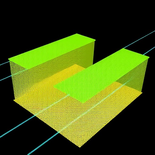
Trains carry people and goods at remarkable speeds, but they also send waves through the ground. These vibrations can travel long distances, disturb residents, rattle buildings and interfere with sensitive instruments used in laboratories, hospitals and industrial facilities. Now, researchers have designed and tested a periodic underground barrier that combines two different vibration-control mechanisms, creating an unusually broad “band gap” in which surface waves are strongly suppressed. Numerical simulations indicate that the barrier can begin blocking vibrations at frequencies as low as 10 hertz and cover a range extending to 80 hertz. In engineering simulations based on real subway and high-speed train measurements at Wuhan station in China, the structure reduced peak ground acceleration by more than 82 percent in both horizontal and vertical directions, with maximum reductions of 85 and 88 percent.
The proposed system belongs to a class of engineered materials known as phononic crystals or elastic metamaterials. Rather than relying only on the mass and strength of a building, these structures manipulate how mechanical waves move through soil. Their repeated geometry creates frequency ranges called band gaps. When a wave falls inside one of these ranges, the periodic structure can reflect it, scatter it, trap its energy or redirect it into forms that rapidly decay. The concept is related to the way photonic crystals control light, although the waves involved here are much slower and travel through soil, concrete and rubber. For railways, the approach is potentially attractive because a barrier can be installed around a protected building or facility instead of being integrated into the structure itself.
The new design merges a wave-impeding block, or WIB, with a trench containing a concrete mass supported by rubber. The trench is periodically repeated through the soil, forming a row of resonant units. In the researchers’ terminology, the first configuration consisted of a concrete trench, a concrete internal mass and rubber that completely surrounded the mass. A second configuration used rubber mainly as a cushion beneath or around the mass rather than fully enclosing it. The third, composite design added concrete WIBs on both sides near the top of the trench. This arrangement was intended to unite Bragg scattering, produced by the repeated barrier geometry, with local resonance, produced by the oscillation of the internal mass on its rubber support.
Those mechanisms operate in complementary ways. Bragg scattering occurs when the wavelength of a wave interacts with the spacing of a periodic structure, causing repeated reflections that interfere destructively with propagation. It generally requires barriers whose size and spacing are comparable to the wavelength being controlled, which can make low-frequency systems large. Local resonance offers a way around that limitation. A relatively small internal mass can vibrate strongly against a compliant rubber element, storing wave energy near its natural frequency even when the resonator is much smaller than the wavelength. The resonant frequency can be approximated by the familiar mass-spring relation, f = (1/2π)√(ke/me), where ke is the effective stiffness of the rubber connector and me is the effective mass of the concrete oscillator. Increasing the mass or lowering the rubber stiffness shifts the resonance downward.
The researchers first examined the concept using a scaled laboratory model. They built three-dimensional resonant units from 6061 aluminum alloy rather than concrete, bonding the components with polyurethane adhesive. The model was placed in a glass box measuring 1 meter long, 0.8 meters wide and 0.6 meters high, filled with compacted sand. The sand had a reported Young’s modulus of 25 megapascals, a density of 1,500 kilograms per cubic meter and a Poisson’s ratio of 0.3. Foam pads around the sides and bottom of the container were used to reduce reflections from the box boundaries. The miniature barriers were arranged in two, three or four rows, while a hammer striking a small shim generated transient vibrations. Accelerometers measured the signals before and after the barrier, allowing the team to compare the frequency content of the transmitted motion.
Across the tested arrangements, the barrier reduced acceleration over much of the 281–450 hertz range. A small amplification near 325 hertz appeared in some measurements, which the researchers attributed to the tiny scale of the model, the limited number of repeated units and interactions between the barrier and the sand. Increasing the number of rows generally improved isolation and reduced the amplification. The team then built a finite-element model of a single repeating cell using COMSOL Multiphysics. The model used Bloch periodic boundary conditions, which mathematically represent an infinitely repeating structure, and a deep soil domain so that surface-wave motion could decay with depth. Its predicted band gap extended from approximately 310 to 450 hertz, broadly matching the experimental attenuation range. Differences between the calculation and experiment were expected because the model assumed ideal, homogeneous, isotropic and linearly elastic materials, whereas the laboratory materials, adhesive joints, sand packing and boundaries were imperfect.
The researchers next analyzed full-scale versions using soil with a density of 1,800 kilograms per cubic meter and a Young’s modulus of 20 megapascals. The periodic spacing was 0.4 meters, the square trench had sides 0.2 meters long, the internal mass and rubber were 0.12 meters wide, and the WIBs were 0.1 meters wide and 0.02 meters thick. Concrete was assigned a density of 2,500 kilograms per cubic meter and a Young’s modulus of 40 gigapascals, while the rubber had a density of 1,300 kilograms per cubic meter, a Young’s modulus of 120 kilopascals and a Poisson’s ratio of 0.47. At 80 hertz, the calculated Rayleigh surface wavelength in the soil was about 0.76 meters, making the barrier’s repeating scale substantially smaller than the wavelength at the lower end of the target range.
The results sharply favored the composite design. The first barrier configuration produced complete band gaps near 57–58 hertz and 65–80 hertz. The second, with a modified rubber arrangement, generated a single complete band gap from 43 to 80 hertz. The third design, combining the resonant trench and WIBs, opened a low-frequency gap beginning at 10 hertz and produced separate ranges of 10–42 hertz and 44–80 hertz. Together these represented a relative band-gap width of as much as 85 percent within the investigated frequency window. The WIBs did not simply add more mass; they altered how waves interacted with the repeating cell. Their ability to reflect and refract surface waves pushed calculated dispersion bands toward nearly flat regions, helping merge attenuation ranges and extend suppression toward lower frequencies.
Modal analysis revealed why the structure worked. In the first two designs, the internal concrete mass carried most of the vibration at the beginning of the locally resonant gap, while the surrounding trench and soil moved much less. The rubber acted as a spring, allowing the mass to oscillate and draw energy away from the passing surface wave. In the composite design, the internal mass displayed lateral, torsional and vertical motion, while the WIBs simultaneously scattered incoming waves. Some energy became localized in the resonant units, but much of it was converted from surface motion into bulk waves that traveled deeper into the soil and dissipated. Changing the WIB’s stiffness or position also altered performance. Horizontally placing the blocks near the top sides of the filled trench produced especially strong effects, lowering the starting frequency and expanding the total calculated band-gap width to about 68 hertz within the 0–80 hertz range.
A larger finite-element model containing 100 repeating units showed that the calculated transmission loss closely followed the predicted band gaps. Outside those ranges, the barrier had little effect and the response remained near 0 decibels. Inside them, transmitted displacement dropped substantially. At 8 hertz, outside the composite barrier’s low-frequency gap, large motion remained along the soil surface whether the barrier was present or not. At 30 hertz, inside the gap, motion continued in front of the barrier but was almost absent behind it. To test conditions closer to reality, the researchers used vibration records collected at Wuhan station during subway operation, high-speed train operation and their combined excitation. The dominant measured frequencies were concentrated between 40 and 80 hertz, falling largely within the composite barrier’s designed attenuation range. Simulations driven by these real signals showed peak horizontal acceleration reductions of 82 percent, 85 percent and 84 percent for the three cases, respectively. Vertical reductions were 85, 87 and 88 percent. The findings remain based on scaled experiments and numerical modeling rather than a full-scale field installation, so soil layering, groundwater, construction tolerances and track–ground coupling will require further testing. Even so, the results suggest that combining local resonance with periodic scattering could provide a compact route to protecting buildings and precision facilities from the growing vibration footprint of modern rail networks.
Cite Scienmag News
Neil Sanderson. (August 27, 2026). Composite Metamaterial Surface-Wave Barriers Improve Isolation of Railway-Induced Vibrations. Scienmag. https://scienmag.com/composite-metamaterial-surface-wave-barriers-improve-isolation-of-railway-induced-vibrations/
Neil Sanderson. "Composite Metamaterial Surface-Wave Barriers Improve Isolation of Railway-Induced Vibrations." Scienmag, 27 August 2026, https://scienmag.com/composite-metamaterial-surface-wave-barriers-improve-isolation-of-railway-induced-vibrations/. Accessed 4 September 2026.
Neil Sanderson. "Composite Metamaterial Surface-Wave Barriers Improve Isolation of Railway-Induced Vibrations." Scienmag. August 27, 2026. https://scienmag.com/composite-metamaterial-surface-wave-barriers-improve-isolation-of-railway-induced-vibrations/