

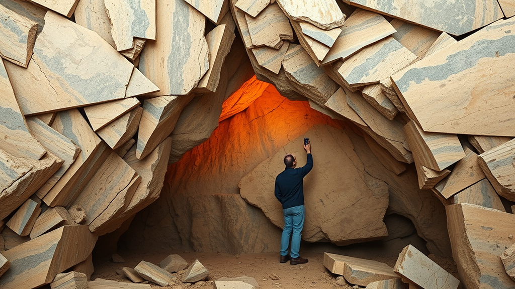
Beneath the folded ridges of China’s Tianmu Mountains, engineers are carving out cathedral-sized chambers in some of the worst ground imaginable: rock shattered into a mosaic of interlocking fragments, squeezed by only modest tectonic stress. A new study of the Liyang Pumped Storage Power Station, published in Environmental Earth Sciences, offers one of the most complete roadmaps yet for keeping such vast underground caverns safe, combining field observation, cutting-edge numerical simulation, classical mechanics, and years of on-site monitoring data into a single validated design framework.
The stakes are considerable. China’s push toward carbon peaking by 2030 and carbon neutrality by 2060 has triggered a nationwide boom in pumped storage hydropower, the backbone technology for balancing an electricity grid increasingly dominated by wind and solar. These facilities rely on enormous underground powerhouse complexes, and statistics from decades of construction show that more than 60 percent of surrounding rock instability accidents in China’s hydropower underground engineering occur in fractured rock mass cavern sections, producing severe delays, enormous economic losses, and occasionally catastrophic safety failures. Understanding precisely how broken rock behaves once engineers hollow out a 25.5-meter-span chamber beneath it is therefore far more than an academic exercise.
The research team, led by Xiao Huang of Zhejiang Ocean University together with colleagues from Jurong Energy and Hohai University, began by cataloguing exactly how the fractured rock at Liyang fails. Field surveys of wedges exposed in grouting and drainage tunnels revealed that most unstable blocks form where two sets of structural planes, one striking northeast and one southeast, intersect near the junction of the cavern spring line and sidewall. These wedges are typically small, under three cubic meters, with triangular pyramidal and pentahedral shapes, while slab-bending failure governed by gently dipping planes dominates the crown. From this evidence the authors distilled three characteristic failure modes: block fall in the crown and upper sidewalls, crown collapse in fault-fracture zones, and sidewall sliding along planes dipping into the excavation.
Each mode has a distinct mechanical signature. Block fall occurs when excavation relieves the tangential compression in the roof, sometimes reversing it into tension, allowing loose blocks to overcome the shear strength of their bounding discontinuities under gravity. Roof collapse develops where intensely fractured rock cannot interlock into a stable load-bearing structure, so shallow strata dislocate and separate as the tensile zone expands and fractures propagate along structural planes. Sidewall sliding is driven by gravity combined with horizontal unloading, sending blocks sliding continuously toward the cavern interior until collapse debris piles at the wall toe. Critically, prior research cited in the study shows that stability under low in-situ stress is governed primarily by the geometry of these discontinuities rather than by the strength of the intact rock itself, which explains why conventional continuum-based design methods struggle in this setting.
To confront that limitation, the team built a coupled Discrete Fracture Network and Discrete Element Method model in the 3DEC code, a 93 by 115 by 20 meter representation in which rock is explicitly cut into blocks by stochastically generated fractures. The synthetic fracture network was calibrated against measured data, with a mean trace length of 4.30 meters, a mean dip of 51.42 degrees, and volumetric fracture density of 1.87 per meter. Rock blocks obeyed a Mohr-Coulomb model while discontinuity contacts followed Coulomb-slip behavior, and a representative elementary volume analysis converted the digital fracture pattern into equivalent rock mass parameters. The vertical stress applied at the model top was just 6.8 megapascals, with horizontal-to-vertical stress ratios of 0.45 and 0.65, capturing the site’s genuinely low-stress regime.
With this model in hand, the researchers optimized the cavern geometry itself, framing shape selection as a stability measure that costs nothing in support materials. Simulating crown rises from zero to ten meters over the fixed 25.5 meter span, they found deformation at the crown mid-span fell non-linearly as the arch steepened: a rise-span ratio of just 0.078 cut mid-span crown deformation by 32.7 percent relative to a flat roof, while a ratio of 0.392 achieved a 44 percent reduction. The arched roof also shrank the high-deformation zone and drew the load-bearing stress arch closer to the cavern perimeter, a hallmark of efficient arching. Because the marginal benefit flattens out, the team recommended a project-specific rise-span ratio of 0.235 to 0.314; the as-built value of 0.304 for the Liyang main powerhouse sits comfortably within it.
Excavation sequence proved equally consequential. Comparing the two industry-standard crown excavation schemes, the simulations showed the pilot-tunnel-first method, which digs two side galleries before removing the central rock pier, reduces permanent crown settlement from 4.91 to 4.00 millimeters even though peak displacement is marginally higher at the temporary floor. The retained central core also shortens the unsupported crown span during early stages, and in practice the side pilot tunnels allow bolts and shotcrete to be installed before the central mass is removed. For cavern group layout, six spacings between the main and auxiliary powerhouses were tested; below 40 meters the stress arches of the two caverns overlap severely and high-displacement zones intersect, while beyond 50 meters further improvement becomes negligible against rising construction costs. The recommended spacing window of 40 to 50 meters brackets the as-built 45 meters.
The study’s most elegant contribution may be its mechanistic explanation of how different support elements actually work, grounded in block beam thrust line theory and compressed arch theory. Fractured roof rock can be idealized as a masonry-like beam of interlocking blocks whose stability depends on the ratio of vertical load to horizontal thrust: when abutment friction is insufficient or thrust too small, the thrust line’s camber rises past the upper boundary of the beam section and the structure buckles. Inclined rock bolts attack this ratio on two fronts, adding horizontal thrust through their anchoring force while shortening the beam’s effective span, driving the thrust line safely downward. Vertical bolts work differently, stitching multiple thin block-beam layers into one thick composite beam whose critical camber for instability, and hence ultimate bearing capacity, is substantially higher.
Dense bolt arrays generate a collective effect described by uniform compression arch theory. Each prestressed bolt creates a conical compressive stress field in the adjacent rock; when bolts are arranged at close spacing across the crown, these cones superimpose into a continuous load-bearing compression ring whose thickness depends on bolt length, spacing, and crown radius, and whose support resistance relates to the average anchoring force through a reduction coefficient below one. Meanwhile, steel mesh reinforced shotcrete arch ribs exhibit a deliberate stiffness evolution, flexible at first to let the rock mobilize its own self-supporting capacity, then rigid as layered shotcrete encapsulates the steel skeleton. This progressive radial confinement transforms shallow rock from a biaxial or even uniaxial state into favorable triaxial compression, lifting its shear strength envelope clear of the Mohr stress circle.
The framework was put to the test on the Liyang main powerhouse itself, a 219.9 meter long, 55.25 meter high city-gate chamber buried under 230 to 290 meters of strata, with rock classified mostly as Grade IV mosaic-fragmented material. The implemented support combines 6 and 9 meter mortar grouted bolts on a 1.2 by 1.2 meter grid, 12 meter prestressed bolts at the arch springing, 20 to 25 meter prestressed anchor cables reaching into deep stable rock, layered steel fiber shotcrete, and steel arch ribs at 2.4 meter spacing, tightened to 1.2 meters in an F54 fault-affected zone. Multi-point borehole extensometers across five monitoring sections recorded the response: cumulative sidewall displacement reached 13.5 millimeters and crown displacement 13.68 millimeters, with displacement rates decaying steadily and no progressive acceleration. A companion 3DEC simulation reproduced the measured pattern with absolute errors between 0.30 and 2.93 millimeters across six near-surface points, a remarkably close match given the stochastic geology. The authors caution that the recommended ratios and spacings are project-specific rather than universal formulas, and that any comparable project must reassess them through its own site investigation, modeling, and monitoring. Still, by welding failure-mode identification, mechanism-based support design, refined DFN-DEM simulation, and full-scale field validation into one coherent method, the study gives engineers building the underground infrastructure of the renewable energy transition a rigorous, proven template for taming broken rock.
Subject of Research: Stability control and support optimization for large-span underground caverns excavated in fractured rock masses under low in-situ stress
Article Title: Stability control and support optimization for large-span underground caverns in fractured rock masses under low in-situ stress
Article References: Huang, X., Yu, Z., Tian, M., Lin, R., Li, Q., & Shi, C. (2026). Stability control and support optimization for large-span underground caverns in fractured rock masses under low in-situ stress. Environmental Earth Sciences, 85(15), Article 389. https://doi.org/10.1007/s12665-026-13124-8
Image Credits: AI Generated
DOI: 10.1007/s12665-026-13124-8
Keywords: underground caverns, fractured rock mass, low in-situ stress, DFN-DEM simulation, pumped storage power station, rock bolts, anchor cables, shotcrete arch ribs, thrust line theory, cavern stability, excavation sequence, rise-span ratio
Cite Scienmag News
Violet Maxwell. (September 21, 2026). Scientists crack the code to stabilizing giant underground caverns in shattered rock. Scienmag. https://scienmag.com/scientists-crack-the-code-to-stabilizing-giant-underground-caverns-in-shattered-rock/
Violet Maxwell. "Scientists crack the code to stabilizing giant underground caverns in shattered rock." Scienmag, 21 September 2026, https://scienmag.com/scientists-crack-the-code-to-stabilizing-giant-underground-caverns-in-shattered-rock/. Accessed 21 September 2026.
Violet Maxwell. "Scientists crack the code to stabilizing giant underground caverns in shattered rock." Scienmag. September 21, 2026. https://scienmag.com/scientists-crack-the-code-to-stabilizing-giant-underground-caverns-in-shattered-rock/