Credit: Space: Science & Technology
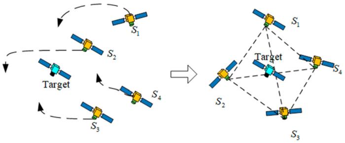
First, authors introduce the spacecraft relative orbit dynamics model, the spacecraft formation relative orbit error dynamics model, and basic theory and lemmas. For spacecraft formation flying, a surrounding control algorithm is designed to let the target be spatially in the convex hull formed by the member spacecraft in the formation. It is a process of the target being surrounded by formation members, as is shown in Fig. 1. The communication between member spacecraft is enunciated through graph theory: definite H = L + B, where L is the Laplacian matrix of system and B describes the communication relationship between the reference spacecraft and the members. For the surrounding mission, it is supposed that the target’s orbital information is known to at least one member of the formation. The spacecraft relative orbit dynamics model is established in the local-vertical local-horizon coordinate system: dxi1/dt = xi2, dxi2/dt = Ai + Ci + ui. The noncooperative target shares similar relative orbit dynamics with members in the formation, its subscript changes from “i” to “nc” when represented. Define Δxi = xi – xnc. The desired position of each member spacecraft to the target is denoted as Δxid. Then, the spacecraft formation relative orbit error is defined as ei = Δxi – Δxid. Combining those equations, de/dt is obviously obtained. In spacecraft formation control, only the information of the neighbors with communication connections can be utilized. To reflect this, the associated formation relative orbit error is defined on the basis of graph theory as ζi1, ζi2. The corresponding error dynamics model dζi1/dt, dζi2/dt, dζ/dt is obtained.
Fig. 1. The illustration of the surrounding control for spacecraft formation.
Then, an observer to estimate the unknown dynamics and a controller to fulfill the surrounding mission are designed. The block diagram of the system is shown in Fig. 2. Unc is unavailable to the spacecraft formation since the target is noncooperative. To estimate its impact on the formation control rapidly, a novel finite-time ESO (FTESO) is developed. The corresponding manifold of the spacecraft formation is defined as s = ζ2 + αζ1 + βζ1p/q where α > 0, β > 0, p, q are odd, and p < q holds. ds/dt can be rewritten as ds/dt = As + BsU + Ds, where Ds is considered as a total disturbance to be estimated. Define a new variable z1 = s. It is considered that z2 = Ds as an extended state. The equation of ds/dt can be rewritten as dz1/dt = ζ2 + αζ1 + βζ1p/q, dz2/dt = W. Define ẑ1 and ẑ2 as the state variables of the observer, then the state equation of proposed FTESO is obtained as Eq. 16. A control law U (see Eq. 29) considering the estimation of D is raised to fulfill the surrounding, whose stability is demonstrated with a propriate Lyapunov function candidate.
Fig. 2. The system block diagram.
Finally, authors illustrate the effectiveness of the controller and the observer through numerical simulations. The parameters of reference spacecraft are a = 42000 km, e = 0.1, and f0 = 0. The target aims to break away from the spacecraft formation by following a weighted-sum-related distance vector. The mission of the spacecraft formation is to surround the target and prevent it from being away in finite time. There are 4 spacecraft in the formation in the simulation. Denote them as S1, S2, S3, and S4 and noncooperative target as Snc. S1 and S3 are available to the reference spacecraft and can obtain the information of noncooperative target. Here gives 2 forms of observers for comparison. One is the linear extended state observer (LESO) based on the auxiliary sliding mode manifold. One other is the proposed FTESO. Results show that both position and velocity error state trajectories of member spacecraft tend to the neighborhood of origin in 160s. The relative trajectories of member spacecraft are shown in Fig. 9. The member spacecraft did not form an enclosure at the beginning, which means that there exists a plane that divides the formation and the target into 2 parts spatially. Then, each spacecraft travels to the desired position obtained through the aforementioned method. Finally, a tetrahedron is successfully formed to surround the target. Comparing the observation error of FTESO to that of LESO, its peak is smaller and has a faster convergence speed. This shows the superiority of the proposed method. In future research, more constraints in practical systems will be taken into account, such as maneuver constraint and collision avoidance between member spacecraft.
Fig. 9. The relative trajectories of member spacecraft to the target.
Journal
Space: Science & Technology
Article Title
Noncooperative Target Finite-Time Surrounding Control of Spacecraft Formation
Article Publication Date
17-Jul-2024


